After much discussion, the SFW TWG agreed that the CRM should be based on a
transonic transport configuration designed to fly at a cruise Mach number of M=0.85 with a nominal lift condition of CL=0.50, and at a Reynolds number of Rn=40 million per reference chord.
They also specified that the wing should have an aspect-ratio of AR=9.0, and a taper-ratio of λ=0.275. Additionally, the span should be sized accordingly to integrate into an existing fuselage model.
The side-of-body is nominally at 10%
semispan and the yehudi break occurs at the 37% station. The trailing-edge (TE) thickness is non-zero to accommodate a minimum-gauge model fabrication constraint of 0.014 inches; at the wingtip, this results in a 0.48% thick TE base.
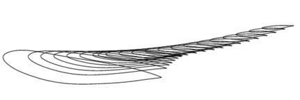
The first figure above depicts a side-view of the airfoil stack as rigged in the fuselage reference plane.
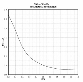
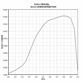
The next figure illustrates the non-dimensional max thickness distribution across the wing; the average non-dimensional thickness of the exposed wing is about 10.8%. The third figure gives the max-camber distribution.
Note that the outboard wing carries supercritical airfoil sections with about 1.5% camber.

The fourth figure shows the wing’s twist distribution and indicates that the wing is washed out about 8 degrees from side-of-body to wingtip.
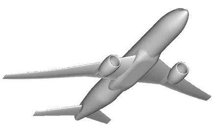
The final figure illustrates the integration of the horizontal tail and nacelle/pylons into the wing/body/nacelle/pylon/horizontal-tail (WBNPH) configuration of the CRM.